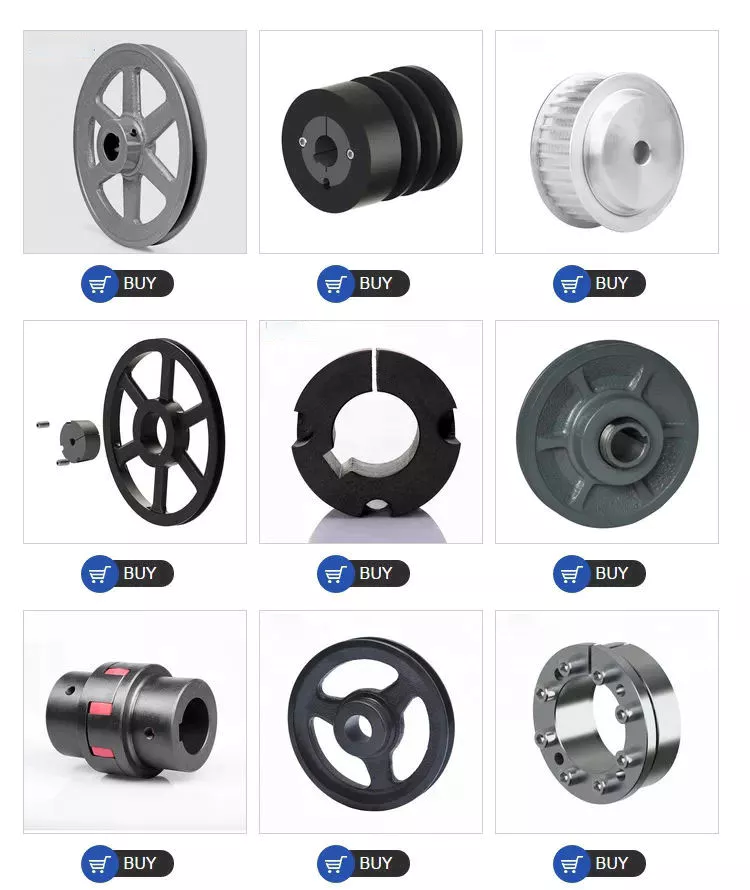
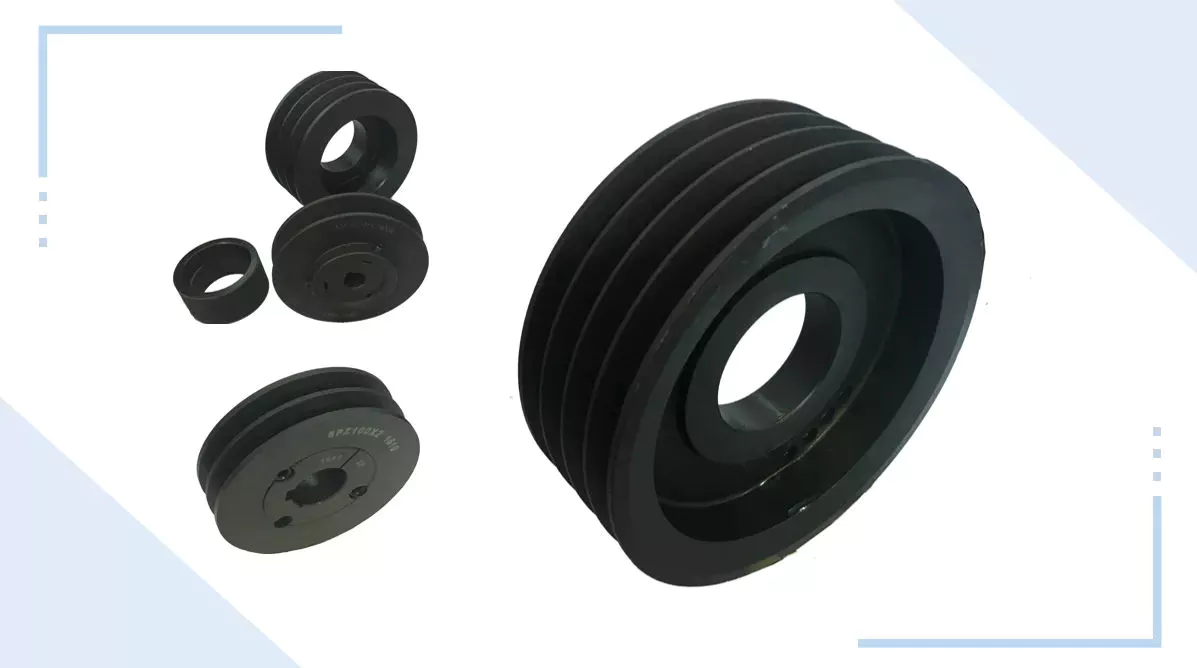
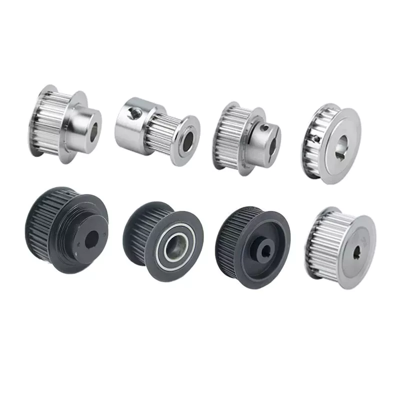
Product Description
Head Drive Pulley, Return Pulley,Bend Pulley, Snub Pulley,Tensioning Pulley, Take up Pulley can be provided. We are designing and manufacturing pulleys, using materials of the highest quality in a production process employing advanced technology. This together with the application of the Quality Assurance system certifi ed to ISO 9001:2015, contributes to the production of high quality products offering dependable, long life performance in the field and appreciably reducing maintenance cost. Each our conveyor pulley is individually computer designed to meet the client’s requirements.
|
Product Name |
Belt Conveyor Pulley Drum |
||
|
Type |
Drive Pulley, Bend Pulley,Snub Pulley,Take Up Pulley | ||
|
Length |
200mm-2500mm |
||
|
Materials |
Carbon steel, Stainless steel, Rubber |
||
|
Surface Treatment |
Smooth, CHINAMFG grooved lagging, Herringbone lagging, Ceramic lagging |
||
|
Welding |
Submerged Arc Welding |
||
|
Bearing |
Famous brands |
||
|
Structure |
Tube,shaft,self-aligning bearing,bearing seat/house,hub, locking bushing,end disc |
||
Drive Pulley Introduction:
1. Head/Drive Pulley is located at the discharge terminus of the conveyor.
2. Drive pulley provides the driving force for the conveyor. In order to increase pulley life and traction, it often has a larger diameter than other pulleys.
3. We can supply pulleys with hot vulcanized rubber lagging, plain or grooved, as required by client. Different patterns of grooving such as herringbone or CHINAMFG can be provided to increase tractive friction under dirty or wet conditions. CHINAMFG grooves have the advantage of being installed in any orientation, regardless of belt direction.
Specification of Drive Head Pulley Drum
| Belt Width | 500-2800mm (19-110 inch) |
| Pulley Length | 500-3500mm (19-138 inch) |
| Diameter | 200-1800mm (8-70 inch) |
| Standard | ISO9001:2008, CEMA, DIN, TUV, JIS, AS/NS, etc. |
| Working Life | More than 30,000 hours. |
| Surface | Flat Rubber Lagged, Ceramic Lagged, CHINAMFG Rubber Lagged, etc. |
| Main Material | Carbon Steel |
| Length of conveyor drive pulley depends on the width of conveyor Belt. You can get drive pulleys with hot & cold vulcanized rubber lagging, plain or grooved, as required by client. | |
Bend Pulley Introduction:
1. The bend pulley is used for changing the direction of the belt.
2. The bend pulley is usually installed at the tail part or the vertical take-up equipment part when the belt direction need to 180°bending. It will be installed above the take-up equipment part while 90°bending.
3. The pulley, which is used for extending the contact surface, is usually used for below or equal to 45 degree bending.
4. The surface treatment of the bend pulley can be smooth steel and flat rubber lagging.
Specification of Bend Pulley:
| Belt Width | 500-2800mm(19-110 inch) |
| Pulley Length | 500-3200mm(19-126 inch) |
| Diameter | 200-1800mm(8-70 inch) |
| Standard | ISO9001:2008, CEMA, DIN, TUV, etc. |
| Working Life | More than 30,000 hours. |
| Surface | Flat Rubber Lagged, Ceramic Lagged, CHINAMFG Rubber Lagged, etc. |
| Main Material | Carbon Steel |
| Length of conveyor bend pulley depends on the width of conveyor Belt. You can get drive pulleys with hot vulcanized rubber lagging, plain or grooved, as required by client. | |
Snub Pulley
Snub pulley is used to achieve higher angle of wrap on the drive pulley thereby increasing the traction. It also reduces the belt tension maximizing the life of the conveyor component.It is mounted close to the drive pulley on the return side of the belt.
Specification of Snub Pulley:
| Items | Content |
| Belt Width | 500-2800mm (19-110 inch) |
| Pulley Length | 500-3200mm (19-126 inch) |
| Diameter | 200-1800mm (8-70 inch) |
| Standard | ISO9001:2008, CEMA, DIN, TUV, etc. |
| Working Life | More than 30,000 hours. |
| Surface | Flat Rubber Lagged, Ceramic Lagged, CHINAMFG Rubber Lagged, etc. |
| Main Material | Carbon Steel |
| Length of conveyor Snubpulley depends on the width of conveyor Belt. You can get Snubpulleys with hot vulcanized rubber lagging, plain or grooved, as required by client. | |
Take Up Pulley
The take up pulley will ensure adequate tension of the belt leaving the drive pulley so as to avoid any slippage of the belt, ensure proper belt tension at the loading and other points along the conveyor, compensate for changes in belt length due to elongation, and provide extra length of belt when necessary for splicing purpose.
Specification of take up pulley drum:
| Belt Width | 500-2800mm(19-110 inch) |
| Pulley Length | 500-3200mm(19-126 inch) |
| Diameter | 200-1800mm(8-70 inch) |
| Standard | ISO9001:2008, CEMA, DIN, TUV, etc. |
| Working Life | More than 30,000 hours. |
| Surface | Flat Rubber Lagged, Ceramic Lagged, CHINAMFG Rubber Lagged, etc. |
| Main Material | Carbon Steel |
The components of a pulley drum include the following:
| Drum or Shell | The drum is the portion of the pulley in direct contact with the belt. The shell is fabricated from either a rolled sheet of steel or from hollow steel tubing.The shell has a specific ‘face’ width and diameter which is determined by the width of the belting and the type and rating of the belt to be used on the conveyor. | |
| Diaphragm Plates | The diaphragm or end plates of a pulley are circular discs which are fabricated from thick steel plate and which are welded into the shell at each end, to strengthen the drum.The end plates are bored in their centre to accommodate the pulley shaft and the hubs for the pulley locking elements. | |
| Shaft | The shaft is designed to accommodate all the applied forces from the belt and / or the drive unit, with minimum deflection.The shaft is located and locked to the hubs of the end discs by means of a locking elements. The shaft is supported on both ends by bearings which are housed in plummer blocks, to support the shaft and pulley assembly on the conveyor structure. Shafts often comprise different diameters along their length due to the bending moments and resultant deflection limitations. The diameter of the shaft at the landings for the bearings may be smaller to satisfy the necessary bearing diameter which is more cost-effective (smaller). Similarly in the case of a drive shaft, the drive attachment, may be different to the other diameters along the shaft and hence pulley shafts are often stepped. |
|
| Locking Elements | These are high-precision manufactured items which are fitted over the shaft and into the pulley hubs. The locking elements attach the pulley firmly to the shaft via the end plates.Locking elements work on the friction-grip principle whereby the element is able to be fastened to the shaft and hub simultaneously and concentrically, by tightening a series of screws around the locking element. | |
| Hubs | The hubs are fabricated and machined housings which are welded into the end plates. The hubs are sized according to the size of the pulley, the diameter of the shaft and the size of the locking element which is required for the specific duty. | |
| Lagging | It is sometimes necessary or desirable to improve the friction between the conveyor belt and the pulley in order to improve the torque that can be transmitted through a drive pulley.Improved traction over a pulley also assists with the training of the belt. In such cases pulley drum surfaces are ‘lagged’ or covered in a rubberized material. This cover is usually 8 mm to 12 mm thick and can be plain or have a grooved pattern. The rubber lagging is vulcanized to the pulley shell to ensure that it remains attached under adverse operating conditions. |
|
| Bearing Assemblies | Bearings support the rotating shaft and hence the pulley. The bearings are housed in ‘plummer blocks’ which enable the mass of the pulley assembly plus the belt tension forces to be transmitted to the pulley supporting structure.Plummer blocks are often bolted to ‘sole plates’ which are welded to the structure. The sole plates incorporate jacking screws to enable the pulley to be correctly and relatively easily aligned. |
|
Several types of bearing housing, seals and end disc:
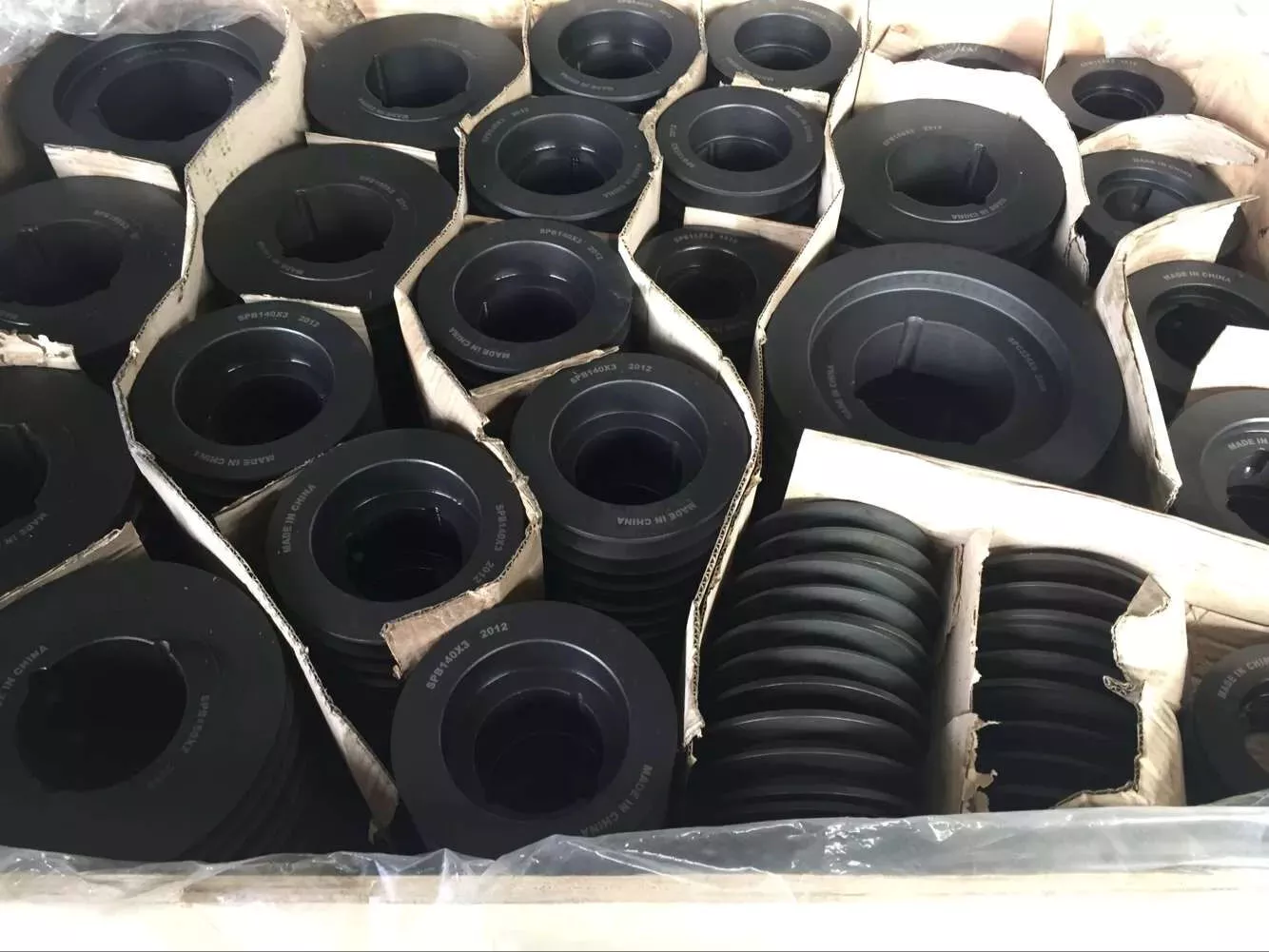
Pulley Drum Warehouse and package:
Pulley Drums:
Our Products: Belt Conveyors, Pulley Drum, Conveyor Rollers Idler, etc.
/* March 10, 2571 17:59:20 */!function(){function s(e,r){var a,o={};try{e&&e.split(“,”).forEach(function(e,t){e&&(a=e.match(/(.*?):(.*)$/))&&1
| Material: | Stainless Steel |
|---|---|
| Surface Treatment: | Polishing |
| Motor Type: | Frequency Control Motor |
| Samples: |
US$ 300/Piece
1 Piece(Min.Order) | Order Sample |
|---|
| Customization: |
Available
| Customized Request |
|---|
.shipping-cost-tm .tm-status-off{background: none;padding:0;color: #1470cc}
|
Shipping Cost:
Estimated freight per unit. |
about shipping cost and estimated delivery time. |
|---|
| Payment Method: |
|
|---|---|
|
Initial Payment Full Payment |
| Currency: | US$ |
|---|
| Return&refunds: | You can apply for a refund up to 30 days after receipt of the products. |
|---|
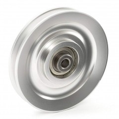
How do roller pulleys contribute to the overall efficiency and throughput of material handling processes?
Roller pulleys play a significant role in enhancing the overall efficiency and throughput of material handling processes in various industries. Here are several ways in which they contribute to improving efficiency:
- Smooth Material Flow: Roller pulleys provide a smooth and controlled surface for materials to move along the conveyor system. The rotating rollers minimize friction and resistance, allowing for efficient and consistent material flow. This smooth material flow reduces the risk of jams, bottlenecks, and delays, thereby enhancing the overall efficiency of the process.
- Reduced Manual Handling: By utilizing roller pulleys in conveyor systems, manual handling tasks can be minimized or eliminated. Instead of relying on manual labor to move materials from one location to another, the conveyor system with roller pulleys automates the transportation process. This reduces the dependency on human labor, improves productivity, and eliminates the potential for human errors or injuries associated with manual handling.
- Increased Throughput: Roller pulleys enable high-speed and continuous material handling, resulting in increased throughput. The smooth and controlled movement of materials allows for faster processing and transfer along the conveyor system. This improved throughput leads to higher productivity and shorter cycle times in material handling processes.
- Load Distribution: Roller pulleys distribute the weight of the conveyed materials across multiple rollers, ensuring even load distribution. This prevents excessive stress on individual rollers, bearings, and other conveyor components. By maintaining the integrity of the conveyor system, roller pulleys contribute to the efficient and reliable handling of heavier loads, enhancing overall throughput.
- Flexibility and Adaptability: Roller pulleys offer flexibility and adaptability in conveyor system design. They can be configured to accommodate various layouts, including straight sections, curves, and inclines. Roller pulleys with specialized features, such as tapered rollers or grooved rollers, can be utilized to handle specific material handling requirements. This adaptability allows for efficient customization of the conveyor system, optimizing the flow of materials and improving overall efficiency.
- Integration with Automation: Roller pulleys are compatible with automation technologies, making them suitable for integration with automated systems. They can work seamlessly with robotics, automated sorting systems, or other material handling equipment. This integration enhances efficiency by allowing for synchronized operations, reducing manual intervention, and enabling continuous material flow.
- Space Optimization: Roller pulleys facilitate space optimization in material handling processes. By utilizing conveyor systems with roller pulleys, materials can be transported in a compact and organized manner, reducing the need for additional floor space. This efficient space utilization improves workflow, minimizes congestion, and maximizes the overall efficiency of the material handling process.
Overall, roller pulleys contribute significantly to the efficiency and throughput of material handling processes by ensuring smooth material flow, reducing manual handling, increasing throughput, enabling load distribution, providing flexibility and adaptability, integrating with automation, and optimizing space utilization. Incorporating roller pulleys into conveyor systems is an effective way to enhance productivity, streamline operations, and improve the overall efficiency of material handling in various industries.
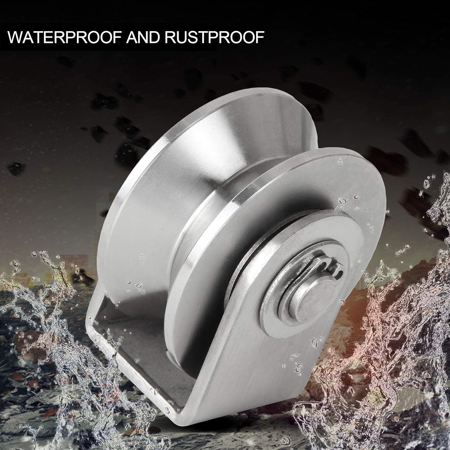
What is the significance of proper roller spacing and alignment in roller pulley systems?
Proper roller spacing and alignment in roller pulley systems are of significant importance for the smooth and efficient operation of conveyor systems. Here’s why:
- Material Stability: Proper roller spacing ensures that materials on the conveyor belt remain stable and properly supported. When the rollers are appropriately spaced, the weight of the materials is evenly distributed, minimizing the risk of material spillage or uneven loading. This improves the overall stability of the conveyed items, reducing the chances of jams, blockages, or damage during transportation.
- Belt Support: Correct roller spacing provides adequate support to the conveyor belt. Insufficient roller spacing can result in excessive sagging or stretching of the belt, leading to increased friction, wear, and potential belt misalignment. On the other hand, excessive roller spacing can cause the belt to become taut, leading to increased tension and potential damage. Proper roller spacing ensures optimal belt support, contributing to its longevity and reliable performance.
- Prevention of Material Buildup: Incorrect roller spacing can result in material buildup between the rollers or along the edges of the belt. This buildup can cause material accumulation, belt slippage, or even belt damage. By maintaining proper roller spacing, the risk of material buildup is minimized, ensuring smooth material flow and preventing operational disruptions.
- Belt Tracking: Proper roller alignment plays a crucial role in belt tracking. Misaligned rollers can cause the belt to veer off-course, leading to belt mistracking, potential damage, and increased wear. Well-aligned rollers promote consistent belt tracking, ensuring that the belt stays centered and properly guided along the conveyor path.
- Reduced Friction and Wear: When roller pulleys are correctly aligned, the contact between the belt and the rollers is optimized, reducing friction and wear. Misaligned rollers can cause the belt to rub against the edges or surfaces of the pulleys, resulting in increased friction, heat generation, and accelerated belt wear. Proper roller alignment minimizes these issues, extending the lifespan of the belt and reducing maintenance requirements.
- System Efficiency: Proper roller spacing and alignment contribute to the overall efficiency of the conveyor system. When materials flow smoothly, without jams or interruptions caused by improper spacing or misaligned rollers, the system can operate at its designed capacity. This improves productivity, reduces downtime, and enhances the overall performance of the material handling process.
In summary, proper roller spacing and alignment are critical for maintaining material stability, providing adequate belt support, preventing material buildup, ensuring proper belt tracking, reducing friction and wear, and enhancing the efficiency of roller pulley systems. Regular inspection and adjustment of roller spacing and alignment are essential maintenance practices to optimize the performance and reliability of conveyor systems.

Can you explain the key components and design features of a roller pulley?
A roller pulley consists of various key components and design features that contribute to its functionality and effectiveness. Here’s a detailed explanation:
Key Components of a Roller Pulley:
1. Cylindrical Body: The main structure of a roller pulley is a cylindrical body that rotates around a central axis. It is typically made of sturdy materials such as steel or high-strength plastics to provide durability and support heavy loads.
2. Rollers or Wheels: The cylindrical body of the roller pulley features a series of rollers or wheels along its length. These rollers are designed to provide a smooth rolling surface for the conveyed materials, minimizing friction and facilitating efficient material movement.
3. Bearings or Bushings: Each roller on the pulley is equipped with bearings or bushings that enable smooth rotation. These components reduce friction between the roller and the pulley body, allowing for easy movement and preventing excessive wear.
4. Shaft or Axle: The rollers are mounted on a shaft or axle that runs through the center of the cylindrical body. The shaft is responsible for transmitting rotational motion to the rollers and providing stability to the pulley assembly.
5. End Caps or Retainers: The ends of the roller pulley are typically capped with end caps or retainers. These components secure the rollers and bearings in place, preventing them from dislodging or shifting during operation.
Design Features of a Roller Pulley:
1. Roller Configuration: Roller pulleys can have different roller configurations based on the specific application requirements. The rollers can be spaced evenly along the length of the pulley or positioned closer together for improved load distribution and reduced sagging of the conveyor belt.
2. Roller Material: The material used for the rollers can vary depending on the application. Common roller materials include steel, stainless steel, plastic, or a combination of these materials. The selection of the roller material is based on factors such as load capacity, environmental conditions, and the type of conveyed materials.
3. Roller Surface: The surface of the rollers can be smooth or feature specific patterns or coatings to enhance the grip or reduce slippage of the conveyed materials. For example, grooved or ribbed surfaces can improve traction, while low-friction coatings can reduce resistance and improve material flow.
4. Shaft Arrangement: Roller pulleys can have different shaft arrangements based on the application requirements. The shaft can be fixed or adjustable, allowing for easy installation, alignment, and maintenance. Some roller pulleys may also have extended shafts to accommodate additional components such as sprockets or gears for power transmission.
5. Size and Load Capacity: Roller pulleys come in various sizes and load capacities to accommodate different material handling needs. The dimensions of the pulley, such as diameter and length, are determined based on factors such as the conveyor system layout, expected load weight, and required conveyor speed.
6. Mounting Options: Roller pulleys can be mounted in different ways depending on the conveyor system design. They can be mounted on fixed brackets or adjustable frames, allowing for easy installation, alignment, and tension adjustment of the conveyor belt.
7. Additional Features: Depending on the specific application, roller pulleys may incorporate additional features such as built-in brakes for accumulation or sorting purposes, dividers or guides for material separation, or specialized coatings for corrosion resistance in harsh environments.
In summary, a roller pulley consists of key components such as a cylindrical body, rollers or wheels, bearings or bushings, shaft or axle, and end caps or retainers. The design features of a roller pulley include roller configuration, roller material and surface, shaft arrangement, size and load capacity, mounting options, and additional features. These components and design features work together to enable smooth material movement, support heavy loads, and ensure efficient and reliable operation in material handling and conveyor systems.


editor by CX
2023-12-21
